|
 |
|
|
Our goal is to build and test an aerosol sampler and sensor that is capable of being deployed from buoys or at other remote sites. We now have a prototype instrument. This project is funded by NSF.
Our goal is to collect aerosols on a filter, move the filter under a
x-ray fluorescence spectrometer and use the XRF to make a quantitative
measurement of the elemental concentrations of aerosols. XRF is a
powerful means of non-destructively analyzing for major and trace elements.
In our case, we would like to analyze for Fe, Ca, Si, K and S in real time
on a set of time-series samples collected over period of weeks to months.
Fe and Si indicate the quantities of mineral dust. Fe is particularly
sensitive by XRF.
 |
 |
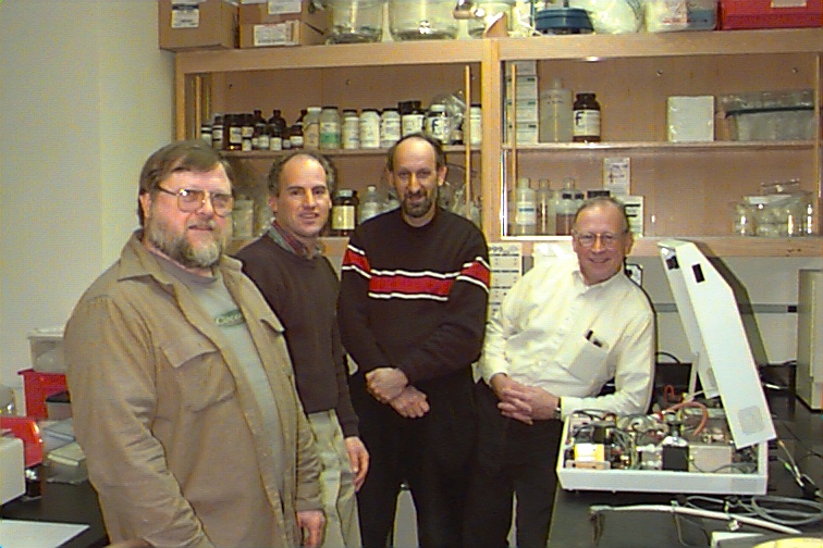
We contracted with Jordan Valley Applied Research Inc. to modify their model EX-310 XRF spectrometer. This XRF can be run off batteries and contains a Rh x-ray tube and an energy dispersive detector. After receiving the JV spectrometer, we dismantled the components of their instrument and rearranged them to fit on top of our aerosol sampler. The two photographs show the xrf components reassembled on top of our aerosol sampler (Al housing). (The flashlight is for scale only.) The JV x-ray tube and detector are contained in the square brass box. The detector, visible on the outside of the brass box, is cooled by pumping (pump in yellow) green antifreeze fluid from a heat exchanger through the detector. Other components consists of a power supply and control boards. The xrf components will be covered with a water tight cover.
Not shown is a module containing air pumps, flow meters and a computer-based controller. This module is similar to the one shown earlier in this web site.
We have built a 24 place aerosol sampler that will allow us to collect and analyze a long time series. Some of the 24 places will contain elemental standards and a XRF calibration filter (Cu, in our case). The 24 place sampler is based on a carrousel that is housed in the Al housing shown in the photographs. We have built sample filter holders which take standard 25 mm filters. One holder can be seen in the photographs gray cylinder with blue o-ring and spring. A filter (not shown in place) is secured in the top of the holder under a thin cap.
Running conditions will be as follows. Each sample holder is placed on the carrousel, moved under the air inlet and push tightly against the air inlet by means of a motor system. After sealing against the inlet, air is pulled through the filter for a set period of time. The air inlet (not in its final form) can be seen on the top of the Al housing at the end of the red tubing. The aerosol-containing filter is then moved under the XRF spectrometer by rotating the carrousel. The filter is then pushed against the XRF by means of another motor system and the XRF turned on for elemental analysis. The same filter can be either be returned to the air inlet for the collection of more aerosols and for a second XRF analysis or a new filter can be used for the next sampling and analysis as part of a time-series.
The motor systems for pushing the sample holder against the air inlet and XRF are white and black cylinders hanging below the Al housing see side view photograph. A third motor system, located in the center of Al housing, rotates the sample carrousel for the time series.
Before we have a fully operational system, much work remains to be done with respect to both hardware and software. A complex software program is needed to allow this sampler/sensor system to run autonomously. One computer will run the XRF spectrometer and another will run the whole sampling and analysis systems. This second computer will link a set of meteorological sensors to the aerosol instrument. It will also extract the pertinent XRF data - counts of Fe etc. for transmission by satellite to a land-based computer. A large set of tests are planned for the spring and summer of 1999, both in the laboratory and in the field.
![]()
Last updated 3/24/99
S. Clifford